
Yea I know, terrible name, but funny in my twisted mind. Build with the ever popular ESP-8266.
The “idea” came to me when my 84 Year old mom fell ill. She has an apartment in a retirement home. They do supply panic buttons, but when she fell sick the one night and activated the panic button, the care takers did responded to her panic button activation (in due time I might add), but I only found out about the indecent the next day as the night staff could not find my number to phone me. I guess communication failure between the day and night staff, who knows….
The design is not all mine, there are a lot of information about this on the Inter-webs, but I tried to “better” the design a bit, Currently the design is a round PCB at about 44mm in diameter, it uses a 500MaH LiPo battery that is rechargeable – take that Amazon AWS..
The charger is supplied as a separate item, I.E. the charging circuit is not build in the design. Initial the design did include the charging circuit, but that increased the thickness of the button with about 7 mm.

The button works like this.
- When the button is pressed for 30 seconds or longer, the ESP8266 goes into AP mode, you then use your smartphone or PC to search and logon to a network called IoT-BuTT.
- Open your browser on your smartphone or PC and goto http://192.168.1.77
- You are then presented with a screen to fill in the Wi-Fi network SSID and password and a URL to activate.
- When the parameters are saved, the IoT-BuTT goes into “normal” mode.
- When the button is then pressed in the event of an emergency, the LED will 1st turn RED, indicating that it is trying to get an IP address from the Wi-Fi network, then start flashing RED every second and it will try and obtain an IP address for 20 times.
- When an IP address is successfully allocated, the LED will flash BLUE and then GREEN when the URL is successfully send.
So what can you do with the button, well….
look at ifttt
IFTTT – is a free web-based service that allows users to create chains of simple conditional statements, called “recipes”, which are triggered based on changes to other web services such as Gmail, Facebook, Instagram, and Pinterest. IFTTT is an abbreviation of “If This Then That“.
Coming soon – An app for Android that will really wake you up, when the elderly presses the button…
So getting into the Nitty Gritty of the IoT-BuTT
Nice thing about the design is that the device is not powered all the time. It will only power on and start to boot when the button is pressed. So this brings battery duration into a complete different level. When pressing the button, the following happens, the button must be pressed for ~2 seconds or until the RGB LED turns RED. This is to compensate for the boot time of the ESP8266 module.
NodeMCU must load 1st and then run init.lua
- GPIO-0 which is linked to CH_PD is set to high when the button is pressed. CH_PD is needed to keep the module enabled after the button press.
- The RGB LED color is changed to RED.
- If there are connection details, (a text file with the URL), load the text file.
- Try and see if Wi-Fi connection is possible.
- RED LED flashes as it tries to get an IP address.
- If no IP is received within ~20 seconds, power the module down.
- If the button stays pressed, remove all the details and shut down, I.E. the next time the module starts up, it will start in AP mode and you will have to reconfigure the SSID, password and URL.
- Once the details are completed, the text file is saved and will be used with the next boot.
- When the module is booted and the text file is loaded and Wi-Fi is available with the ssid and password specified, IoT-BuTT will try and connect using the details.
- If an IP address is available, the RGB LED is changed from RED to BLUE
- The ESP8266 then creates a TCP socket and sends the URL from the text file.
- The RGB LED is changed from BLUE to GREEN.
- The ESP8266 then waits a couple of seconds and sets GPIO-0 to low. This will also pull CH_PD to low and the module is powered down.
- Some ESP8266 seems to ignore the set GPIO-0 to low, so a transistor is connected to the RGB LED GREEN leg that pulls GPIO-0 to low via a capacitor and resistor
On to the build stuff then
I found it easier to use think wire on all the ESP8266 pins, insert a short piece of wire at each leg, fit the ESP8266 and solder the bottom side 1st


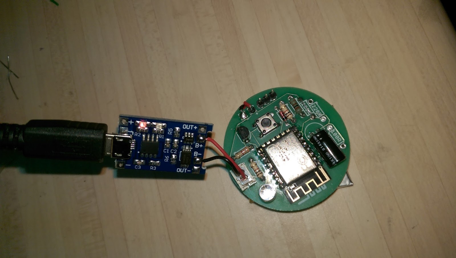
Solder all the other components, The 220R and 180R resistors are for the ADC pin, so you may use them for determining the Voltage level of the battery, Below is the IoT-BuTT connected to a USB Li-Po charger, I've got it connected to a 500Mah Li-Po


To program the ESP8266, you would need one of these
SparkFun FTDI Basic Breakout - 3.3V
VERY important , must be the 3.3V one
This is a basic breakout board for the FTDI FT232RL USB to serial IC.
The pinout of this board matches the FTDI cable to work with official
Arduino and cloned 3.3V Arduino boards.
- The positive is supplied by the battery, the negative, pin on the right, connects to the FTDI negative or ground - Green jumper wire in the picture
- Orange wire - RX (middle pin) on the IoT-BuTT goes to the TX pin on the FDTI
- Yellow wire - TX (left pin) on the IoT-Butt goes to the RX pin on the FDTI


IoT-BuTT connected to a LiPo USB Battery charger

Fully charged LiPo

The program is NodeMCU that gets loaded, use this to load the NodeMCU firmware
LuaLoader is a Windows program for uploading files to the ESP8266 and
working with the Lua serial interface. It is compatible with all
versions of Windows from Windows 95 to Windows 10.
No comments:
Post a Comment
Note: only a member of this blog may post a comment.